Description
💡 Light up your life with precision and power – don’t get left in the dark!
- MULTIPLE DIMMING MODES - Choose from PWM, PSM, trailing, or leading edge dimming to customize your lighting experience.
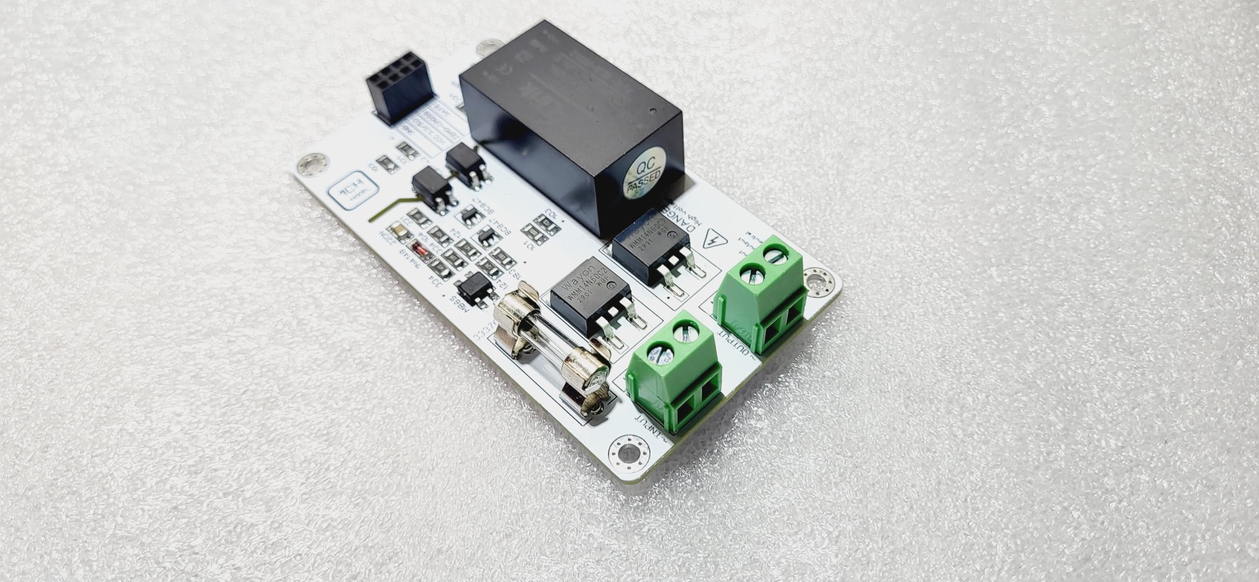
- COMPACT VERSATILE DESIGN - Space-saving 50x90mm PCB fits effortlessly into any setup, elevating your lighting control game.
- PRECISION AMBIANCE CONTROL - Tailor your lighting with ultra-smooth, flicker-free dimming for both incandescent and dimmable LEDs.
- ROBUST 500 W POWER HANDLING - Power through your lighting needs with high-capacity output supporting diverse applications.
- SEAMLESS MICROCONTROLLER INTEGRATION - Plug & play compatibility with Arduino, Raspberry Pi, ESP8266, ESP32 – perfect for smart home and DIY projects.
The MOSFET Trailing Edge AC LED Light Dimmer by IotMug delivers precise, flicker-free dimming compatible with incandescent and dimmable LED bulbs. Supporting up to 500W output and multiple dimming methods, it integrates seamlessly with popular microcontrollers like Arduino and Raspberry Pi. Its compact design and versatile compatibility make it ideal for professional and DIY smart lighting projects.