⚙️ Drive Your Innovation Forward with Precision & Control!
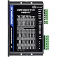
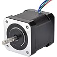
This integrated stepper motor driver and controller board supports NEMA 17 and 23 motors, offering forward/reverse rotation, 4 control modes including UART, and 9 preset workflows. Featuring an HD LCD for real-time parameter display and memory retention, it enables precise, versatile motor management for professional and industrial applications.


R**D
Used an external foot switch connected to the controller
I wanted to use a foot switch to turn on & off a Nema34 stepper motor for a coil winder. I wanted a digital display that showed speed in RPMs, and could could directly connect to the motor without needing a separate driver. My motor is rated at 6A, but for my use case (10-150RPM), it only draws about 1A from a 24VDC power supply. The current increases at certain speeds (1.9A max at 350 RPM, & 1.4A at 999 RPM). Seems non intuitive to me, but probably normal behavior for any given stepper motorTo mimic pressing any of the controller’s front panel buttons, I found 5 pins located on the left side of the PCB (directly under the 3 subdivision switches). These pins are marked GND, STOP, CCW, CW, and OUT. I used a multimeter, and with no power source connected, determined that the STOP, CCW, and CW pins are electrically connected in parallel with the front panel switches. The panel switches, when pressed, connect the the appropriate pins to the GND pin. There is no OUT button so this pin is somewhat of a mystery. It’s labeled as “reserved” in a diagram on Amazon’s description page for the product. Throughout my testing it showed no AC or DC voltage with respect to GND, and has a 2.5 Meg resistance to the GND pin when the controller has no power connection.To easily access the 5 pins with a soldering iron, I decided to remove the PCB from the case. This wasn’t absolutely necessary, but it made it much easier for me to wrap & solder 26AWG wire to the the pins. I carefully cut between the case and the silicone blobs on the PCB where they held it to the case. With the blobs cut, I pulled up the PCB to reveal yet another PCB that it was socketed to. The corresponding socket on the PCB beneath is marked with the same text as the male pins on the top PCB, with the exception of the OUT pin which was marked as FAN.With the top PCB removed, I soldered 5 short wires from the board to a 6 pin 0.1” pitch male header. I bent the wires connected to the header to the board so that it stood vertical. I then cut a thin piece of plastic to insulate the bottom of the header from the PCB. After checking continuity between the header pins and the PCB pins, I hot glued the plastic insulator to the PCB board and then hot glued the bottom of the header to the plastic (see photos).After reseating the top PCB back onto the bottom PCB, I powered up the controller and verified that shorting the CW, CCW, & STOP header pins to the GND using the header pins mimicked the front panel buttons.I use work mode 3 (F-01 set to P03), which essentially uses the CW, CCW, & STOP buttons to stop and start the motor for an indefinite period of time. Speed is adjusted by the rotary encoder on the front panel. I only needed a CW rotation for the coil winder, so I ultimately connected just the GND and CW pins on the header to a normally open SPST foot switch. Momentarily pressing the foot switch turned on the motor in the clockwise direction. Momentarily pressing the foot switch again stopped the motor.I figured I’d likely house the controller in a case some day, so I attached two 6 pin 0.1” female sockets to the ends of a short piece of ribbon cable making it easy to detach and reattach these connections to the controller (see photos).So far the setup works really well and I’m happy with the functionality. One thing I did notice was that the heat sink started to get really hot at certain RPM settings. Whenever I delivered more than around 1.5A to the motor for extended periods, the controller ultimately went into thermal shutdown and stopped the motor. After the controller cools down sufficiently, it comes back to life and works just fine. This controller is rated at 4A, but I suspect if you want to drive a motor with higher than about 1.5A, you’ll likely need a fan to cool it down if you’re running it for long periods of time. One hint to this issue is the mysterious FAN/OUT pin. This pin is also marked “reserved” on a diagram in the Amazon product description. My best guess is that it transitions from LOW level (0V) to a HIGH voltage level (3.3V?) when the controller gets too hot. This could connect to gate of MOSFET to run a small fan. I haven’t tested this theory as I don’t want to intentionally overheat the controller :).Overall this controller has lots of features and has a nice easy to read display. Like other reviewers have said, most of these extra features are great for testing stepper motors. It worked great for my project!
A**.
Amazing For Robotics
My husband is a gadget geek and loves making anything Halloween related. When I saw this Stepper Motor Driver Controller Integrated Board, I knew he needed to try it. Robotic Halloween props are a specialty of his, as he has made skeletons that play guitars and a fortune telling that moves her head.He found this stepper motor to be very versatile. It is great value for the money, being very budget-friendly. He has tried several stepper motors, and this is one of the better ones.He has found this one is best for lightwork and is super easy to control with precise movements. It is highly reliable, with fantastic speed control. It is a quick start with no delays and accurate positioning. The low torque speed provides a good low-speed workflow.The possibilities are endless with this stepper motor. Currently, he is working on a werewolf for a Halloween light show that moves. While it takes a long time to build the props, the stepper motor is one thing that makes them come to life so our guests will have the fright of their life.
M**E
Great little driver, though with a learning curve.
The media could not be loaded. Admittedly I am a bit under-experienced when it comes to stepper motor applications and also their associated controllers so keep that in mind with this review please.So anyways this stepper drive controller is awesome with its many uses. You can set forward speed, back speed, steps (Essentially Distance Traveled.) Multiple pattern types (Pulses, Forward and Back, etc.) how many times it repeats a pattern up to infinitely, control the motor with the potentiometer, control it with buttons only when held or toggle on and off and the list goes on.These are all features built right into the board and the applications for it can go on and on. It really is awesome, however it takes a bit of a steep learning curve at first to decipher everything with the menus and such. I took about an hour to get the hang of everything, hopefully though I can save you that time by a large part.My first major issue was trying to figure out why there were two completely different tables on the instructions that seemed to be accessed the same way in the menu and had overlapping values meaning they were impossible to set right...Well that was a misunderstanding on my part. When you press the potentiometer in the menu it originally brings you into is the ‘Parameter’ menu so you need to look at the parameter table just to start off.The default value you’ll see come up is F-01 which is the associated value on the parameter table. By rotating the potentiometer you can change the value from F-01 through F-13. And those will all correspond to what they do on the “Parameter Table” specifically. For example Rotating the potentiometer to F-03 brings up your forward speed value under it.To select and change it you click the potentiometer in and it will cycle you through the changeable values with each click. Rotating the potentiometer up and down will increase or decrease the highlighted value. Click it enough and you’ll Get back to the F-XX value that can be changed again to access the other Parameter options. Or at any point you can press and hold the potentiometer for 3 seconds and be taken back to the starting menu.F-05 allows you to Change Reverse Speed and so forth…Now the secondary table which is the “Work Mode” table. This is actually a submenu sort of selection as part of the “Parameter Menu.”When you first press the potentiometer in and you are brought into the parameter selection menu and it will be on the default value of F-01. And will have a value below it of likely P-01. But can be any P-XX value in general.That P-XX value is the value to change the “Work Mode” so in other words that P-XX value is what corresponds to now specifically the “Work Mode Table.” So to change it, first make sure you are on F-01 and then press the potentiometer in and change to P-XX value to 01-09 to correspond with the work mode you want. Then press the potentiometer in until it takes you back to the main display.So for example F-01 (1st on the function table) with a value of P-02 puts the board into a work mode where the motor spins when you hold the CW button. And goes the opposite way if you hold the CCW button.If you go to F-01 / P-03 it will now do the same thing but stay on after the button is pressed until you press the button again. The stop button. Or a button to go the opposite direction.The other Work Modes are much more advanced and too much to try and go into here. Just reference the tables and maybe play with them a bit to get an idea.In the “Work Mode Table” when it says something like it will continue for “F-06” loops; what it is saying is it will loop the amount of times you set the value to in the F-06 “Parameter Menu.” Same for F-02 (Pulse Number/Distance) and so forth.The work modes have no value to be set themselves, everything they use is from the Parameter (F-02 - F-13) menus. Remember that and it will save you a ton of time and confusion.I have included some pictures of the instructions with this review for reference in case you lose yours or just want something to get an idea of this all before buying so I hope that will be of help :)Another issue I had was trying to figure out why some of the work modes weren't doing forward and back and such like they were supposed to. Another tip is you might need to set your forward and back position delay (F-07 and F-08) to something other than 00. I was having issues with it at that value not progressing to the next Phase of the Work Mode. For example it goes forward then just stops instead of going forward, back, forward, back and so forth.I think that it’s because 00 is handled as infinite on this board so it was never finishing the phase? No idea. But again any value other than 00 works.Other than that a couple of other tips is if you are running this a lot you might want to cool it a bit with a fan as the controller can get hot under continuous duty. Alternatively adjusting the current level down using the potentiometer is good to help keep it cool.The value should be whatever the lowest you can go with your motor where it still works for what you need. A sign of it not having enough power would it be not turning at all, or skipping steps which is usually heard with a clicking noise.Everything aside I am excited to put this controller to use for some projects of mine. I am very happy with it. Hopefully the info here will be useful, thanks for reading!
N**K
Works great, one glaring annoyance.
This thing works great and is easy to wire. Plenty of canned cycles for whatever use you may have. Control + Driver all in one.Only big miss is that it won't hold the stepper "braked" when idle (like say a CNC machine). You can kind of cheat with a very long delay on some of the cycles, but that's kind of annoying. If they were to release a version with a brake, it'd be an easy five stars. Well worth the money.
S**F
Great unit at a great price
Excellent little stepper motor controller. Simple with more options than you're going to need but definitely worth the price.
Trustpilot
1 day ago
5 days ago